Posted on

How to install active cooler for Raspberry Pi 5

The Raspberry Pi 5 is a significant upgrade in terms of power and performance, which makes it ideal for resource-intensive applications such as gaming, programming, and media projects. However, with greater performance comes the challenge of managing heat, and that’s where an active cooler (like a fan or cooling tower) becomes essential to maintain optimal performance.
What You’ll Need:

  • Active cooler (fan or cooling tower designed for Raspberry Pi)
  • Small screwdriver (usually Phillips head)
  • Thermal paste or thermal pads (optional but recommended for better heat transfer)
  • A small power supply (depends on the cooler’s power needs, but it’s usually powered via GPIO pins)

Step-by-Step Installation Guide

  • Step 1: Power Off and Unplug Your Raspberry Pi 5
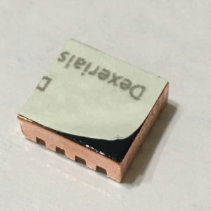
  • Step 2: Peel off the protective films from the thermal pads, and attach three thermal pads to the Raspberry Pi 5

  • Push the push-pins through the holes on the active cooler.

  • Position the Active Cooler onto the Raspberry Pi 5, ensuring a precise alignment with the dedicated heatsink holes. Push the push-pins through to secure them into place.

  • Connect the cable to the fan connector found on the Raspberry Pi 5

Posted on

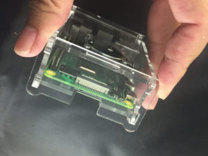
How to Assemble Raspberry Pi 4 Acrylic Case

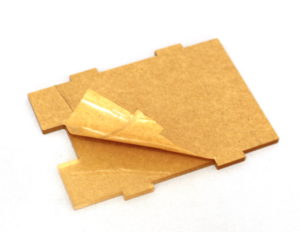
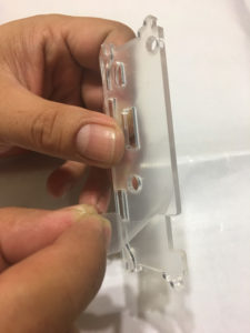
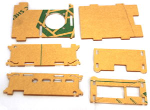
Before assembly, please remove all the protective films from the acrylic pieces. Note that there are films on both side of the pieces. If the film is not removed, it may affect the assemble process.

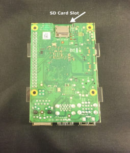
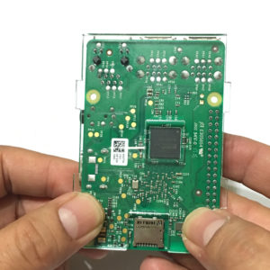
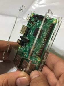
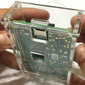
Place the base plate on the Raspberry Pi 4 board. Align the memory chip and TF card slot position correctly.

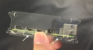
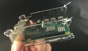
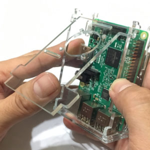
Position the HDMI side plate, slotting it into the tabs on the bottom plate. Make sure align the mini USB port,  two mini HDMI ports, and audio port with the holes on the side plate.

Position the second side plate, slotting it into the tabs on the bottom plate.

Make sure the round holes on both side plates are at the same height.

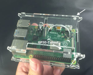
Install the top plate. Insert the two tabs of the top plate into the holes on the two side plates. Make sure the cutout on the top plate align with the GPIO ports.

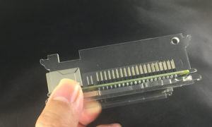
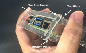
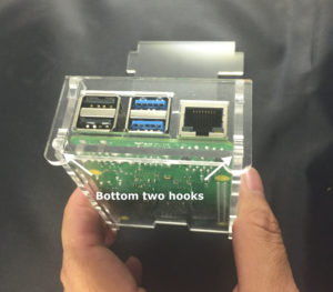
Assemble the USB plate. Slide the top of the USB plate over the two top hooks first.  Then, using very light pressure, pivot the USB plate downward over the bottom two hooks. Gently press the bottom two hooks and slide the USB plate into the place.  If you encounter ANY severe resistance, stop! Do not force this piece or you will break the plastic. Back off, check the alignment of the other pieces (especially the HDMI side), and try again. Gently.

Similarly, install the TF card plate using the same technique. Top to bottom.

Finally, check the lid make sure it can be opened and closed freely. GPIO cutout is aligned correctly. All the round feet facing downward.

Posted on

How to Assemble Raspberry Pi 3 Black ABS Case

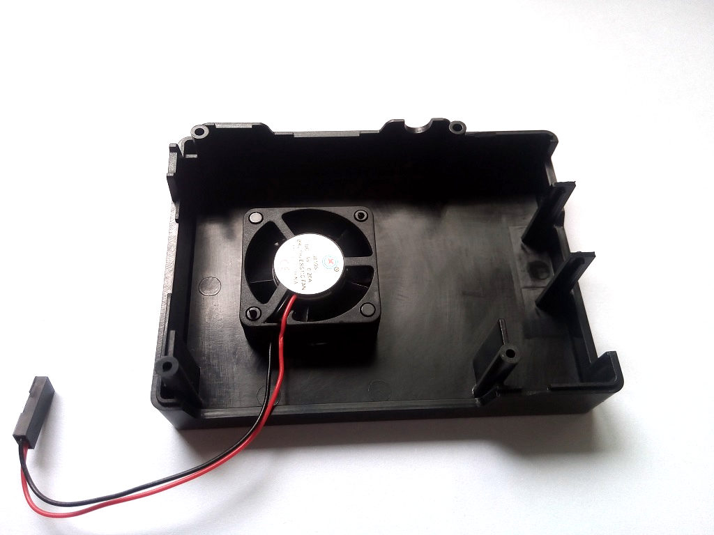
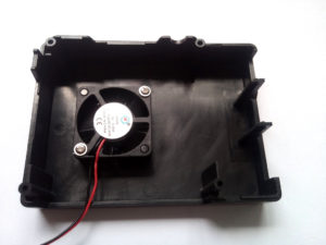
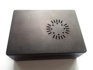
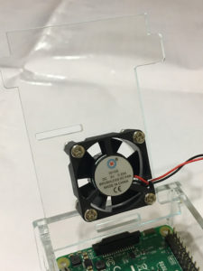
Take out the upper case (the one with fan holes) from the package.

Align the fan with the four posts, note the sicker side of the fan should be facing up.

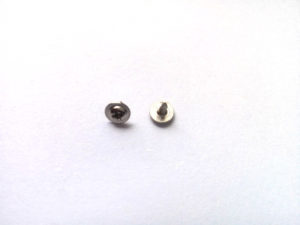
Secure the fan using two screws with washers.


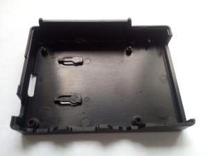
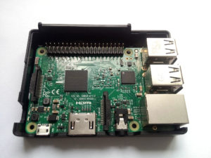
Take out the lower case from the package. Place the Raspberry Pi board into the lower case. Note there are posts on the lower case used to align the board. Make sure the Ethernet and HDMI openings align correctly to the corresponding ports on the Raspberry Pi board.

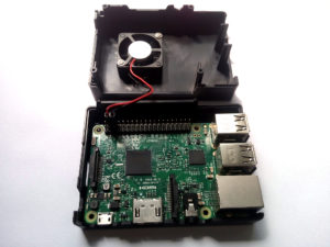
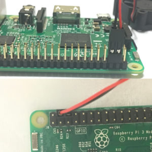
Connect the wires of the fan to the Raspberry Pi GPIO. Note the positions of the red/black wires. The red wire should be on the first row, second pin from left.

Fit the upper and lower case together.

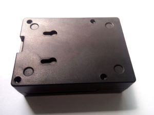
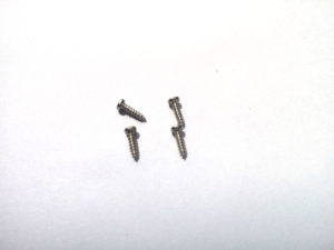
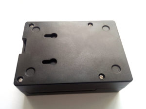
Use 4 small screws to secure the upper and lower case together.

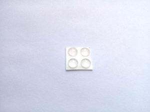
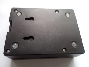
Take out the four rubber pads from the package. Stick them to the two indented circle on the bottom of the Raspberry Pi case.

The assembling of ABS case is finished.

Posted on

How to install driver for Arduino boards with CH340g USB to serial converter chip

Some of the Arduino Uno or Nano boards use CH340g USB to serial converter chip. If your system does not have the driver installed, it may cause some issues when you connect your Arduino board to the computer. The arduino IDE may not be able to detect the board you connected.

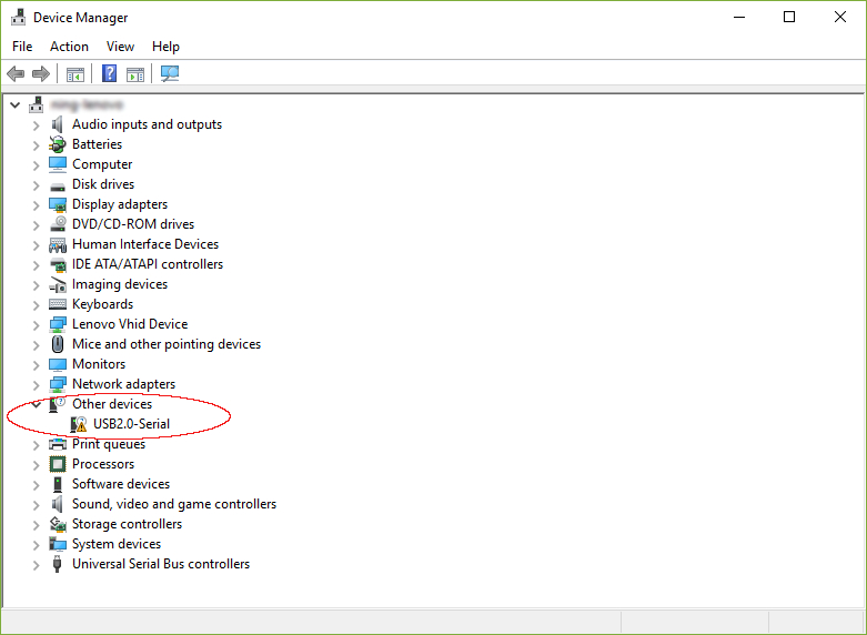
After you connect Arduino board to your PC, go to “Device Manager”, if you see the picture bellow shows “USB2.0-Serial” under “Other devices”, that indicates the CH340g driver has not been installed to your system.

The problem can be solved by installing the CH340g driver. You can download the driver for CH340g from the manufacturer’s official website:

http://www.wch.cn/download/CH341SER_EXE.html

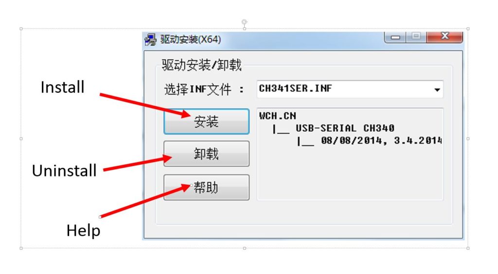
Click “DOWNLOAD”, a file named “CH341SER.EXE” will be downloaded to your computer. Then simply double click the exe file, It should open a dialog box shown below. Click “INSTALL”

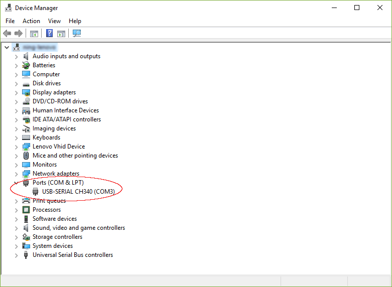
The installation will take a few minutes. After installation is done, go to “Device Manager” and check if you can see the “USB-SERIAL CH340 (COM19) under “Ports” (see picture below).

Now the driver for CH340g is installed successfully. You can connect your Arduino board to your PC, the Arduino board should be detected without problem.

Posted on

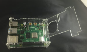
How to Assembly Raspberry Pi 3 Acrylic Case

Remove the protective films on the acrylic sheets. Note that there are films on both side of the sheet. If the film is not removed, it may affect the assemble process.

Place the base plate on the Raspberry Pi 3 board. Align the memory chip and TF card slot position correctly.

Insert the two side plates to the base plate. Align the HDMI and microUSB power ports. Make sure the round holes on both side plates are at the same height.

Install the lid. Insert the two bumps of the lid into the holes on the side plates. Make sure the cutout the lid align with the GPIO ports.

Assemble the USB plate. Make sure the two round feet face downward. Insert the protrusions of the side plates into the slots on the USB plate. Do not use excessive force, it may break the case.
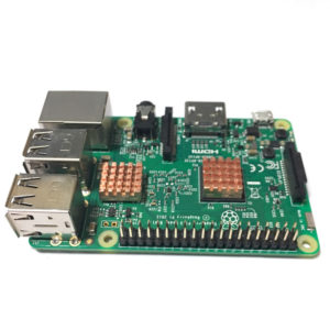
Similarly, install the TF card plate. Make sure the round feet face downward. Align the TF card slot.
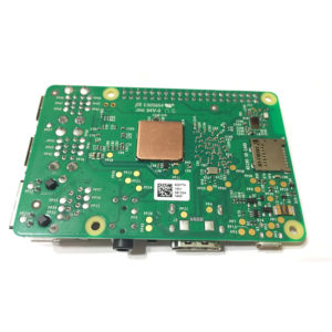
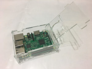
Finally, check the lid make sure it can be opened and closed freely. GPIO cutout is aligned correctly. All the round feet facing downward.